Getting Started
Quick Start
JetKVM
Installation
Getting your JetKVM up and running is easy. Follow these steps to start controlling your target computer remotely.
- Attach the USB-C port on the back of the JetKVM to a USB port on the computer you wish to control.
- Plug a Mini HDMI cable from the HDMI port on the JetKVM to the target computer's HDMI port.
- Insert an Ethernet cable into the Ethernet port on the JetKVM to connect it to your network.
- Plug in the JetKVM. Once powered, the front display will show the device's IP address.
- Open a browser and enter the IP address displayed on the JetKVM screen.
You can now control your target computer remotely.
Front Display Overview
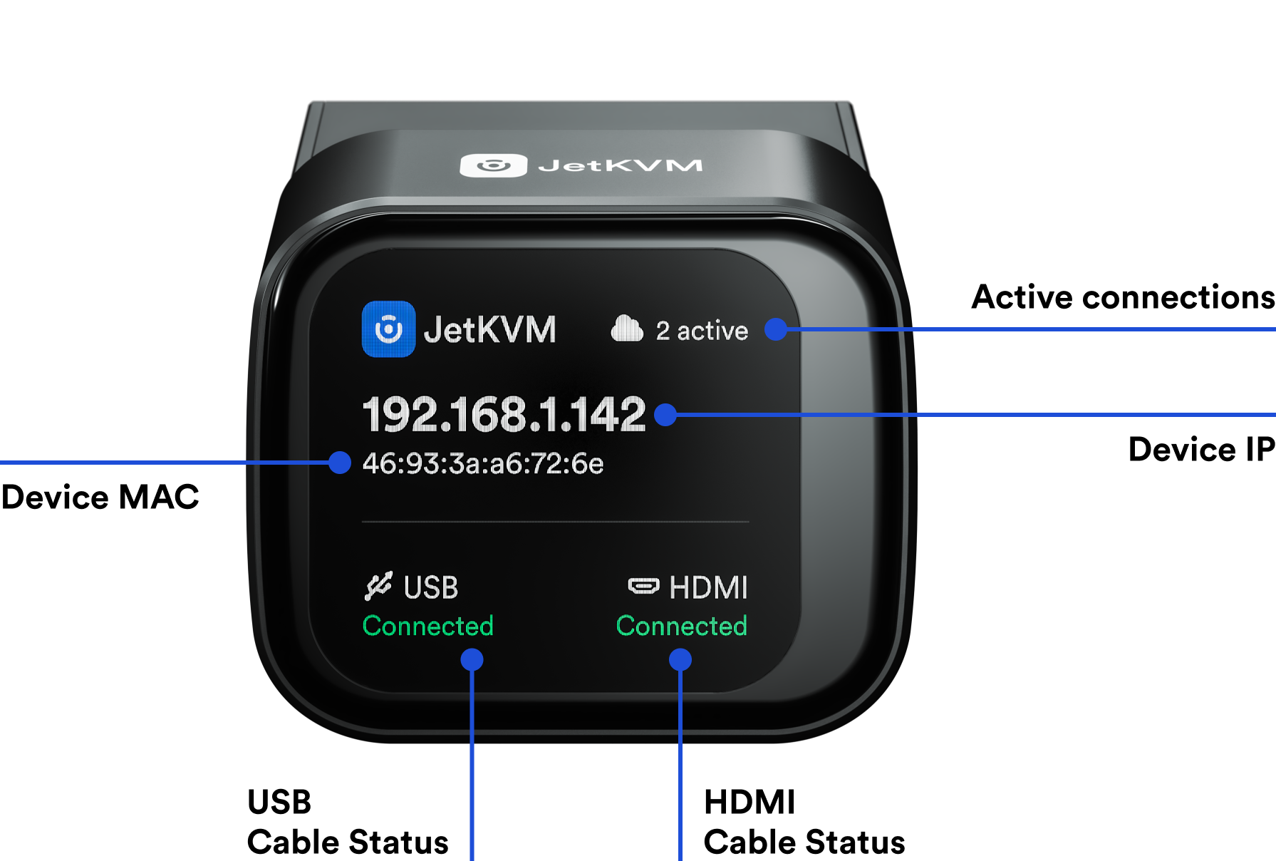
The front display of the JetKVM provides key information at a glance. Here’s what each section of the display shows:
- Device IP: The IP address assigned to your device by the network, allowing you to access the web UI.
- Device MAC: The unique MAC address of the device.
- Active Connections: Displays the number of active connections currently in use.
- HDMI Cable Status: Shows whether the HDMI connection to the target computer is active.
- USB Cable Status: Indicates whether the USB connection to the target computer is active.
This information helps you quickly verify if your JetKVM is properly connected and ready for remote management.
Ports Overview
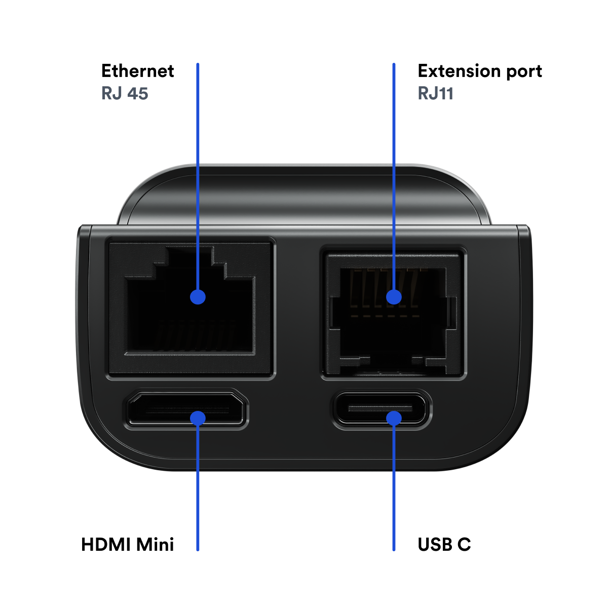
Here's a look at the available ports on your JetKVM device:
- USB-C: For connecting to the target computer.
- HDMI Mini: For receiving the video signal from the target computer.
- Ethernet - RJ45: For network connectivity.
- Extension Port - RJ11: For additional features like ATX power control, Serial Console access, or AC/DC power control.
ATX Power Control Extension
The JetKVM ATX Power Control Extension allows you to remotely power on, reset, and monitor your PC - without losing your front panel buttons and LEDs. This guide walks you through installing it safely and clearly.
- ATX Extension Board - Extension board with USB-C and RJ12 ports that mounts inside PC case like a slot card
- RJ12 Cable - Links ATX board to JetKVM device
- PCIe Slot Cover Brackets - Brackets for routing in different case sizes (standard and small options)
- Ribbon Cables - Female-to-female connectors used to link the ATX board to your motherboard’s
F_PANELheader.
Installation
1. Power Down and Prepare Your PC
Let's make sure everything's safe before working inside your case.
- Shut down your PC completely through the operating system
- Flip the PSU switch to OFF (usually located on the back of the power supply)
- Unplug the power cable from the wall or power strip
- Ground yourself by touching something metal (like the case frame)
- Set up your workspace with tools and lighting nearby - you'll mainly need a Phillips screwdriver
2. Mount the ATX board in the case
Let’s physically install the board in a free slot. We include two bracket sizes, choose the one that fits your case the best.
- Pick any empty PCI/PCIe slot opening (it doesn’t use electrical contacts, just mounting space).
- Slide the board in and secure the metal bracket with a screw.
3. Connect ATX Extension to motherboard
Locate the F_PANEL header on your motherboard. It’s usually a small white or black 9- or 10-pin block labeled F_PANEL, PANEL1, or FP1.
If you've previously connected your front panel controls to your motherboard, disconnect them from the motherboard now (we'll reconnect them later).
Using your motherboard manual as a reference, identify the specific layout and polarity of your motherboard pins to match and connect it with the labels on the JetKVM ATX Board.
This step is a common source of installation errors, so take extra care to match both the pin layout and polarity (+/-) with the labels on the JetKVM ATX Board. If you don't have your motherboard manual handy, you can usually find it by searching for your motherboard model number followed by "manual" online.
Make sure that you get the layout & polarity(+/-) on all the pins. It matters.
4. Connect the Case Front Panel Cables (Optional)
If you want to have control of your computer from the front panel, you'll need to connect them to the JetKVM, which will forward the signals to the motherboard.
These cables are typically soldered directly to the case and terminate in female ATX pin connectors, usually labeled for power, reset, and LED indicators.
In the previous step, we likely disconnected these cables from the motherboard. Now, connect them to the corresponding pins on the JetKVM ATX board using the pinout guide below. Be sure to match the polarity(+/-) on the LED Pins - proper polarity is essential for it to work correctly.
| JetKVM ATX Board Label | Front Panel ribbon cable Label | Polarity(+/-) Matters? |
|---|---|---|
| BTN PWR + / – | Power SW | No |
| BTN RST + / – | Reset SW | No |
| LED HDD + / – | HDD LED | Yes, check manual for polarity |
| LED PWR + / – | Power LED | Yes, check manual for polarity |
Make sure that you get the layout & polarity(+/-) for LED HDD & LED PWR. It matters.
Now that everything is connected, head over to the JetKVM web interface by entering the device’s IP address in your browser. In the JetKVM toolbar, click on “Extension” to access the ATX controls. If everything is configured correctly, you should now be able to power on, reset, or shut down your PC remotely - directly from the JetKVM interface.